Alamat
No 1, Jalan Yd, Distrik Huishan, Kota Wuxi, Jiangsu. 214183
Jam Kerja
Senin sampai Jumat: 09.00 - 17.00
Sabtu: 09.00 - 16.00
Alamat
No 1, Jalan Yd, Distrik Huishan, Kota Wuxi, Jiangsu. 214183
Jam Kerja
Senin sampai Jumat: 09.00 - 17.00
Sabtu: 09.00 - 16.00


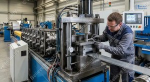
A roll forming machine punching die installation is the process of fitting, aligning, and timing a punching tool on a roll forming line so holes, slots, notches, and service cutouts land in the right place on every profile. Done right, the die runs for hundreds of thousands of strokes before re-sharp. Done wrong, the same die produces torn edges, drifting hole positions, and a stripped stripper plate in the first shift.
Punching die installation definition: a controlled setup procedure that includes die set leveling, pilot pin fit, punch to die clearance check, stripper plate shimming, and punch to forming line timing calibration. The output is a hole that lands in the same spot on the strip within plus or minus 0.2 mm across the full coil.
We have installed lini mesin pembentuk rol in more than 20 countries over the last 15 years, and the punching station is the place where most week one callouts come from. The line is straight, the rolls are clean, the profile is correct, and the holes are out of position. Nine times out of ten the cause is the punching die installation, not the roll tooling. This guide covers the five alignment tips that fix that problem on day one.
Punching is the only operation on a roll forming line that cuts metal cold, in motion, at high speed. A 30-station line running 30 m per minute produces a punch stroke every 30 to 60 mm. If the die drifts by even 0.3 mm, the hole position drifts the same amount on every profile. Customers see a straight strip with crooked holes, and the line gets blamed for a tooling problem.
The real failure list, in order of how often we see it on commissioning:
Each one of these is a 15 minute fix if you know the symptom. Each one is a full day of troubleshooting if you do not. The five tips below cover each failure in the order they should be checked.
| # | Tip | Tool needed | Time | Pass criteria |
|---|---|---|---|---|
| 1 | Level the die set to the line centerline | Precision level, dial indicator | 20 min | Runout under 0.05 mm across die face |
| 2 | Set punch to die clearance for the material | Feeler gauge, micrometer | 15 min | 5 to 10 percent of stock thickness per side |
| 3 | Time the punch to the roll line encoder | Encoder readout, strobe | 25 menit | Hole position within plus or minus 0.2 mm |
| 4 | Shim the stripper plate to parallel | Feeler shims, dial indicator | 15 min | Strip drag under 5 N at full speed |
| 5 | Verify pilot pin and strip feed | Pin gauge, caliper | 10 min | Pilot engaged before punch contact |
Total setup time on a clean line is around 90 minutes. Add 30 minutes if the line has been running other profiles and the strip is misaligned in the entry guide.
The die set is the steel block that holds the punch and die in position. It must sit parallel to the line centerline, both across the strip travel and along it. A 0.1 mm tilt across the die face shows up as a 0.1 mm shift in hole position between the first and last strip in a coil.
Step by step:
A CNC roll forming machine with a servo punch can sometimes hide a 0.2 mm die tilt by adjusting the punch trigger on the fly, but that just moves the wear to the punch itself. Fix the die first, then time the punch.

Clearance is the gap between the punch and the die wall on each side. Too tight and the punch rubs and breaks. Too loose and the slug pulls sideways, leaving a burr on the hole edge and a bent punch on the heavy stock. The standard rule for cold roll forming mild and galvanized steel is 5 to 10 percent of stock thickness per side.
| Stock thickness | Clearance per side | Total punch to die gap |
|---|---|---|
| 0,4 mm | 0.02 to 0.04 mm | 0.04 to 0.08 mm |
| 0,6 mm | 0.03 to 0.06 mm | 0.06 to 0.12 mm |
| 0,8 mm | 0.04 to 0.08 mm | 0.08 to 0.16 mm |
| 1,0 mm | 0.05 to 0.10 mm | 0.10 to 0.20 mm |
| 1,2 mm | 0.06 to 0.12 mm | 0.12 to 0.24 mm |
| 1,5 mm | 0.075 to 0.15 mm | 0.15 to 0.30 mm |
| 2,0 mm | 0.10 to 0.20 mm | 0.20 to 0.40 mm |
| 2,5 mm | 0.125 to 0.25 mm | 0.25 to 0.50 mm |
For stainless steel 304 and 316, drop the lower end of the range by 1 to 2 percent. Stainless work hardens fast and a tight clearance tears the edge. For aluminum and ZINCALUME, hold the middle of the range. The full proses pembentukan gulungan dingin guide covers why stock behavior changes the math.
Check clearance with a feeler gauge on the punch entry side, not the bottom. The entry side is where the cutting happens, and a low reading there means a tight cut and a long die life.

This is the alignment step most commissioning teams get wrong on the first try. A servo roll forming punch reads its trigger from the same encoder that drives the line, so the punch fires when the strip has moved a set number of pulses. A hydraulic punch reads from a mechanical cam or a proximity switch, which has its own lag.
The right way to time either system:
A common trap is to time the punch at full speed on the first run, then find that creep speed testing later puts the hole in the wrong place. Time at creep first, then verify at full speed. The roll forming process basics article covers how strip speed affects cut length, and the same physics applies to punch timing.
For lines making baki kabel profiles with multiple slot patterns, the punch fires several times per profile length. Each station has its own timing offset, and the offsets must add up so the slot pattern matches the cut length. Log the offsets per profile recipe, and never copy a delay value from one profile to another without rechecking.

The stripper plate sits over the die and holds the stock flat while the punch retracts. If the stripper plate is not parallel to the die face, the strip climbs the punch on the upstroke and either bends the punch or tears the strip edge. Both end the die life in a single shift.
Setting the stripper plate:
A parallel stripper plate also controls the slug. When the plate is flat, the slug drops straight through the die cavity and out the bottom of the die set. When the plate is tilted, the slug catches on the die edge and either jams or scratches the next strip. Either way, scrap rate climbs before hole quality drops, which makes it easier to catch the problem early.

The pilot pin is the small post that engages a previously punched hole to keep the strip from drifting sideways before the next punch fires. On a pallet rack line running tab and slot patterns, the pilot pin is what keeps the slot centered in the profile. If the pin is missing, undersized, or worn, the slot walks 1 to 2 mm per meter of strip, and a 6 m rack upright ends up with a slot that misses the beam hook.
The pilot pin must be a sliding fit in the stripper bush, never a press fit. A press fit wears the bush in a week. A loose fit lets the strip drift. The right fit is 0.02 to 0.05 mm clearance between the pin and the bush on the diameter, and full engagement depth at least equal to the stock thickness.
After fitting the pin:
Untuk pembentukan gulungan khusus profiles with multiple hole patterns, the pilot pin often needs a different diameter for each profile. Keep a pin kit for every profile in the line, and label the pins by profile code. Mixing pins between profiles is a fast way to break a stripper bush.

Hydraulic and servo punches reach the same hole quality, but they get there through different setup paths.
| Setup step | Hydraulic punch | Servo punch |
|---|---|---|
| Pressure setting | 80 to 120 bar for 0.5 to 1.5 mm mild steel | Not applicable, force is programmable |
| Punch stroke time | 0.2 to 0.4 sec fixed by hydraulic flow | 0.05 to 0.15 sec set on HMI |
| Timing reference | Mechanical cam or prox switch | Encoder pulse count |
| Stripper force | Spring set, fixed | Spring or nitrogen cylinder, adjustable |
| Terbaik untuk | Heavy gauge, thick stock, structural profiles | High speed, accurate hole position, multi-pattern |
| Stroke rate limit | 60 to 90 strokes per minute typical | 200 to 400 strokes per minute possible |
A hydraulic punch on a 2.0 mm pallet rack upright profile needs the full pressure range and a slower cycle to cut clean. A servo punch on a 0.5 mm drywall stud line runs at three times the cycle rate and lands the slot within 0.1 mm on a 6 m length. The servo roll forming article covers the controls in detail.
The alignment tips in this guide apply to both. What changes is the timing reference and the stripper force adjustment. Hydraulic punches need a cam timing check, servo punches need an encoder delay entry. Both need the stripper plate shimmed to parallel.
These are the five symptoms we see every week on commissioning. Each maps to one of the five alignment tips, and each has a 15 to 30 minute fix on the line.

Punch life on a roll forming line depends on three factors: clearance, lubrication, and stock quality.
Clearance is set at installation. Get it right and the punch lasts 500,000 strokes on mild steel. Get it wrong and the punch lasts 50,000.
Lubrication is the variable most plants skip. A light film of press oil on the strip before the punch station drops punch wear by 30 to 40 percent. For roofing and cladding lines running galvanized stock, a wipe-on application at the entry guide is enough. For stainless lines, use a chlorinated oil to prevent work hardening on the cut edge.
Stock quality is the third factor, and the one no one controls. A coil with a hard spot from a cold-rolled edge will kill a punch in one shift. Incoming inspection with a file test or a portable hardness tester catches hard edges before they reach the punch. ASTM A653 covers the standard for galvanized stock, and the hardness should stay under 65 HRB for a punch to survive a full coil.
Re-sharpening is a planned event, not a failure. Most plants re-sharpen the punch every 200,000 strokes on mild steel, and rotate two punches so there is always a sharp one ready. A pembentukan gulungan khusus line with a punch library and a re-sharp schedule runs years without a tooling crisis.
A modern line places the punching station after the first 3 to 5 roll stands, so the strip is flat and tracked before the hole is cut. Some lines mount the punch inline with the rolls, and others mount it on a side carriage that the strip passes through. The carriage mount is easier to access for die changes, but the inline mount holds tighter tolerances.
| Tata Letak | Terbaik untuk | Toleransi | Waktu peralihan |
|---|---|---|---|
| Inline in roll stand | High speed, tight tolerance | Plus or minus 0.1 mm | 60 to 90 min |
| Side carriage | Multi-profile, frequent changes | Plus or minus 0.3 mm | 20 hingga 30 menit |
| Standalone press before line | Heavy gauge, structural | Plus or minus 0.5 mm | 45 to 60 min |
For most roofing, cladding, and purlins, inline mounting holds the best accuracy. For saluran penyangga and racking, where profile changes happen weekly, a side carriage is the practical choice. The cara kerja mesin pembentuk gulungan guide covers where the punching station fits in the full line layout.


Apa Itu Instalasi Cetakan Pukulan pada Mesin Pembentuk Gulungan? A...
Baca selengkapnya

Proyek mesin pembentuk rol di AS bermuara pada tiga kendala utama:...
Baca selengkapnya
Kualitas setiap lini pembentukan rol bergantung sepenuhnya pada...
Baca selengkapnya
Apa Itu Program Pelatihan Operator Mesin Roll Forming? Bagaimana...
Baca selengkapnya English English
  Español
 Português
 Русский
 العربية
 Bahasa Melayu
 Türkçe
 ไทย
ไทย
 Bahasa Indonesia