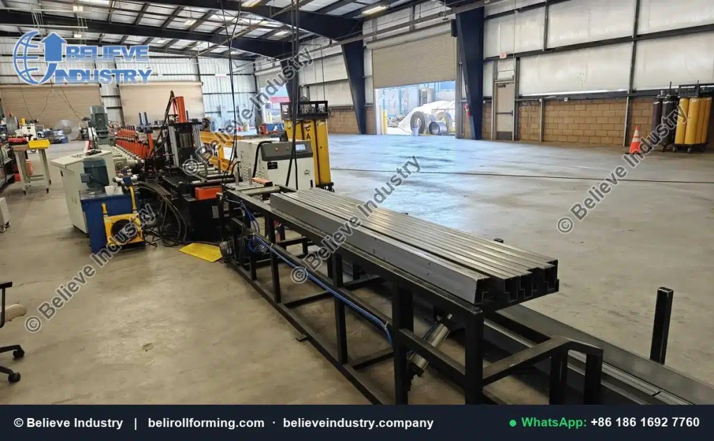
Step beam roll forming line and run out table used for step beam roll forming defects inspection

Step Beam Roll Forming Defects: 6 Fixes for Bow and Twist

ต้องการเครื่องมืดโปรไฟล์สำหรับโครงการของคุณหรือไม่
รับใบเสนอราคาฟรีจาก Believe Industry — ผู้ผลิตเครื่องม้วนรูปตามสั่งมากกว่า 15 ปี
ขอใบเสนอราคา ดาวน์โหลดแคตตาล็อก

Step Beam Roll Forming Defects: Bow, Twist, and Beam Sag Fixes

Keywords: step beam roll forming defects, beam bow fix, beam twist, edge wave step beam, beam sag, roller station adjustment, step beam straightness, forming defect fix, rack beam QC

Short answer

Step beam roll forming defects are shape errors that show up along a finished pallet rack beam. The common ones are vertical bow, side camber, twist, edge wave, step height drift and end flare. Most step beam roll forming defects start in four places: the coil, the roll gaps, the cut off unit and the run out table. Fix them in that order, and fix one thing at a time.

A 3 m rack beam with 2 mm of vertical bow will not seat in the upright slots without force. A beam with 2 degrees of twist will not hold a pallet level. The numbers in this article come from shop acceptance records on step beam lines delivered by Believe Industry to more than 50 countries since 2005, plus measurement practice described by MHI และ steelconstruction.info. They are shop figures, not catalogue claims.

ส่วน general bow and twist guide covers common profiles. This page stays with step beams. The stepped flange, the 28 station pass schedule and the welded end connector change both the cause and the fix of step beam roll forming defects.

What are step beam roll forming defects?

A step beam is the horizontal rack member with a rolled step that supports a shelf or a wire deck. A typical line forms 1.5 to 2.5 mm strip in 80, 100 or 120 mm beam depths across about 28 powered stands, then punches, cuts and welds a connector at each end. The production sequence lists the stations in order.

Definition: step beam roll forming defects are measurable departures from the beam drawing that the forming line creates, including bow, camber, twist, edge wave, step height drift and end flare, as opposed to damage added later by handling, stacking or welding.

That distinction matters. Beam sag under load is a design check. Beam sag seen on the run out table is a support problem. Both get blamed on step beam roll forming defects, and only the second one belongs on this list. The step beam versus box beam comparison shows how the section shape changes which error appears first.

step beam line uncoiler and leveler

Six step beam roll forming defects and the limits that catch them

Measure before you adjust. A feeler gauge, a 3 m straightedge, a string line and two digital levels cover nearly every case of step beam roll forming defects. Record the reading before each change, then run three 3 m beams and measure again. A reading taken from memory is not a record.

ข้อบกพร่องHow it looksวิธีวัดShop limit over 3 m
Vertical bowBeam arches up or down3 m straightedge plus feeler gauge at mid span1.5 มม.
Side camberBeam curves toward one sideString line along the step edge1.0 มม.
การบิดSection rotates along its lengthTwo digital levels at the beam ends1 องศา
ขอบเป็นคลื่นStep flange ripples between stands300 mm straightedge on the flange0.3 mm peak to valley
Step height driftStep depth changes along the beamวัดด้วยคาลิเปอร์ 3 จุดบวกหรือลบ 0.3 มม.
End flareLast 100 mm opens after cut offCaliper across the open end0.5 มม.

Rack design guidance such as EN 15620 and the RMI material published by MHI uses a deflection limit near span/200 under rated load. That is a load test on a finished beam. It is not a straightness tolerance, and mixing the two is a common reason step beam roll forming defects get misdiagnosed.

Where step beam roll forming defects start

OriginWhat changesDefect it producesตรวจสอบอย่างแรก
ม้วนCoil set, crown, slit camber, residual stressSide camber and long bowMeasure 2 m of slit strip on a flat table
เครื่องรีดเรียบ Uneven roll penetrationBow that reverses at every cutCompare front, middle and tail of one coil
แท่นขึ้นรูปLeft and right roll gap mismatchการบิดDial gauge on both shaft ends
Pass scheduleToo much bend in one standEdge wave on the step flangeCount the stands that carry a bend
การสปริงกลับOverbend too smallOpen step angle and slow twistMeasure the angle 10 minutes after forming
การตัดClamp force, blade impactEnd flare in the last 100 mmMeasure the cut end before the welder
Run out tableToo few supports under a long beamBeam sag that looks like forming bowAdd one support and measure again

Coil problems cause more step beam roll forming defects than worn rolls do. A coil with crown across its width pushes more metal through one side of every stand. The strip leaves the line longer on that side, and the beam curves toward the shorter edge. Check the coil before you touch a roll. A new supplier or a new heat number is enough to change the reading on a line that ran clean for six months.

Roll gaps and the 28 station pass schedule

A step beam line spreads the bend over about 28 stands. Each stand adds a few degrees. A gap difference of 0.05 mm between the left and right side of one stand is enough to put a visible twist into a 3 m beam by the last station. The error is small at stand 8 and large at stand 28 because every later stand inherits it. Gap errors are the second most common source of step beam roll forming defects.

Set the last forming stand first. Work upstream, one stand at a time, and run three beams after each change. Adjusting four stands at once gives four new variables and no way to tell which one helped. This is the part of step beam roll forming defects that takes patience, and it is the part most often skipped during commissioning.

Polished rolls matter on pre galvanized strip. A rough roll face drags one flange harder than the other and adds twist. The Metal Construction Association technical library has useful notes on tooling finish for coated steel. For thick 3.0 to 5.0 mm coil, the gaps and shaft sizes change again, as the heavy duty step beam guide explains.

step beam forming roll gap adjustment

Springback, overbend and beam sag

Steel springs back after every bend. High strength coil at 350 MPa yield springs back more than mild steel, usually 2 to 4 degrees on the step flange. The last two stands add a small overbend so the section relaxes to the drawing angle. Too little overbend leaves the step open. Too much closes it and pulls the web out of flat. Overbend errors belong to step beam roll forming defects that appear only after the strip relaxes.

Measure the angle twice: once at the exit and again 10 minutes later. A section that keeps moving after it leaves the stands has residual stress, not a bad roll. Engineering reference data on modulus and yield helps set the first overbend estimate before you cut tooling.

Beam sag on the run out table is different. A 3 m beam of 2 mm strip is light, but it will droop between two supports spaced 2.5 m apart. Add a third support and the sag disappears. Sag that disappears with a support is not one of the step beam roll forming defects, and no roll change will fix it.

Cut off, end notching and weld distortion

The cut off unit can add defects after the forming stands are correct. A hydraulic stop and cut holds the line to 3 to 4 m/min and clamps the section hard. A flying saw tracks the moving beam at 20 to 35 m/min and never stops the strip. A press in the line usually gives 10 to 15 m/min sustained. Ask which figure a supplier means before comparing lines. Our คู่มือใบมีดตัดแบบเคลื่อนที่ covers the two drive types.

Clamp pressure and blade alignment show up as end flare. End flare is one of the step beam roll forming defects a buyer can see without instruments. Measure the last 100 mm before the connector is welded. The end notching and hole processing article lists the punch and cut rules that keep the end square.

Welding the end connector adds heat on one face of the beam. On a thin step beam that heat pull shows as local twist at the first 150 mm. A double station welder with a fixture holds both ends flat while the weld cools. If the twist appears only after welding, the forming line is already correct and step beam roll forming defects are not the cause.

The adjustment order that removes step beam roll forming defects

Do not start with the straightening head. It will press a bad beam into a straight shape while leaving the cause in the pass schedule, and the defect returns on the next coil. Use this order.

ขั้นตอนActionMeasure afterMove on when
1Check coil crown, slit camber and coil set2 m of strip on a flat tableCamber under 1 mm over 2 m
2Verify base flatness and stand alignment2 mm over 3 m along the lineFoundation and stands read true
3Set leveler penetration evenly on both sidesStrip at entry and exitNo coil set left at the first stand
4Adjust the last forming stand, then walk upstream one stand at a timeThree 3 m beams per changeBow and twist within the table above
5Add overbend for springback at the final two standsAngle at exit and 10 minutes laterAngle holds within 0.5 degree
6Only then set the straightening headThree more beamsNo new marks on coated strip

Step 2 is where many plants lose time. A base that has settled moves one stand out of plane, and every later stand follows it. The foundation requirements guide gives the flatness and anchor figures. The installation guide covers the alignment sequence after the concrete cures.

One change, three beams, one measurement note. That habit resolves most step beam roll forming defects in a single shift. Six changes at once usually takes three days.

Straightening head or roll correction

The table below separates step beam roll forming defects by where they start. Read it before booking a service visit.

หัวปรับตรงRoll gap correction
FixesResidual bow after formingTwist, edge wave and step drift at the source
Speed of change10 to 20 minutesTwo to four hours per stand pass
RiskMasks a bad pass schedule and marks coated stripSlow, needs measured passes
Lasts untilThe next coil changeThe next tooling wear cycle
Use whenForming stands already measure trueAny defect that repeats every beam

A straightening head is a finisher. It is not a repair station for step beam roll forming defects that come from a bad coil or a settled base. On pre galvanized strip, heavy pressure also polishes a visible track into the zinc layer.

finished step beam bundle end profile

Acceptance records to keep

A buyer should be able to ask for the numbers, not a photo of a straight beam. Record these on the factory acceptance test before shipment. These six readings describe step beam roll forming defects in numbers a supplier cannot argue with later.

  • Straightness: bow and camber on three 3 m beams from the front, middle and tail of one coil
  • Twist: two level readings per beam, in degrees over 3 m
  • Step height: caliper at 250 mm from each end and at mid span
  • Length: plus or minus 1 mm with a servo flying cut off, plus or minus 3 mm with a hydraulic stop cut
  • Hole position: plus or minus 0.5 mm from the beam end, checked against the punch and die setup
  • Angle: measured at exit and again 10 minutes later

ส่วน step beam machine overview has the profile and tooling figures. The how to choose a roll forming machine guide shows how to write these checks into a purchase order. A supplier who cannot produce this record has not measured step beam roll forming defects on a real coil.

คำถามที่พบบ่อย

Q: What causes vertical bow in a step beam?

Coil set and uneven leveler penetration cause most vertical bow. A crowned coil feeds more metal through one side of the stands. Check 2 m of slit strip on a flat table before adjusting any roll. Vertical bow is one of the step beam roll forming defects that reverses from the front of a coil to the tail.

Q: How do I tell twist from beam sag?

Lay the beam on three supports and read both ends with a digital level. Twist stays after you level the supports. Sag disappears when you add a support. That one test separates handling damage from step beam roll forming defects in about two minutes.

Q: Can a straightening head fix step beam roll forming defects?

It removes residual bow after the forming stands are correct. It cannot fix twist from a roll gap mismatch or edge wave from a bad pass schedule. Using it first hides the cause, and step beam roll forming defects return on the next coil.

Q: What straightness tolerance should a rack beam hold?

Our shop acceptance uses 1.5 mm of bow and 1.0 mm of camber over 3 m, with twist under 1 degree. Your rack design may set tighter limits, so put the numbers in the purchase order. Straightness limits for step beam roll forming defects belong in the contract, not in an email after shipment.

Q: Why do step beam roll forming defects appear after a coil change?

A new coil brings a different crown, yield strength and residual stress pattern. The same roll gaps produce a different beam. Re measure three beams from the new coil and reset the leveler before touching the stands. Most step beam roll forming defects blamed on worn rolls are actually new coil problems.

Q: How long does a roller station adjustment take?

One stand takes 20 to 40 minutes including three test beams. A full pass across 28 stands takes two to four hours. A complete line overview with motorised width adjustment shortens the width change, not the straightness check. Time spent here is cheaper than shipping step beam roll forming defects to a rack installer.

Where to go next

Start with a profile drawing, one coil certificate and a straightness limit written into the order. Our เครื่องคลายคอยล์และป้อนยืดเรียบ page describes the entry equipment that removes coil set, and the upright rack page shows the mating column slots. Step beam roll forming defects are cheaper to prevent at the enquiry stage than to tune out after commissioning. Send a drawing and a coil spec, and our engineers will mark the stands that need the first measurement.

Last updated: 2026-11-16

บันทึกการเปลี่ยนแปลงบทความ

2026-11-16: Initial publication in the 2026-11-16 calendar slot. Six defect families, measurement limits, root cause map, six step roller adjustment order, straightening head comparison, acceptance records and 6 FAQ.

เงื่อนไขทบทวนครั้งถัดไป

EN 15620 or RMI guidance revision; new straightness readings from shipped step beam lines; quarterly SERP check for the focus term; a change of coil supplier or steel grade in the 1.5 to 2.5 mm range.

สารบัญ