roll forming machine workshop before installation

Roll Forming Machine Installation: 7 Steps To Production 2026

Need a Roll Forming Machine for Your Project?
Get a free quote from Believe Industry — 15+ years of custom roll forming manufacturing.
Request a Quote Download Catalogue

Roll Forming Machine Installation: 7 Steps From Foundation to First Good Profile

Short answer: Roll forming machine installation is seven jobs done in order. Survey the floor, cast the foundation, set and level the line, align the rolls, connect hydraulic and electrical systems, dry run without coil, then thread the first coil. A 15 to 25 m line takes 5 to 10 working days with two fitters, one electrician and a crane on the buyer side. Two drawings decide most of the outcome: the anchor bolt plan and the mill base level.

Buyers often treat roll forming machine installation as a two day handover. It is not. A roll forming machine installation moves a 15 to 25 m chain of separate machines onto one straight pass line. A 1 mm error at the uncoiler becomes a twisted profile at the exit.

This guide covers the work on site, from concrete to the first saleable part. It does not repeat the roll forming machine line component list, and it leaves concrete mix design to the civil engineer.

What Roll Forming Machine Installation Covers

A shipment is a set of modules. The uncoiler and straightener feeder is one, the punch press another, the forming mill another, then the cut unit and the auto stacker. Roll forming machine installation joins them into one line and proves that strip runs through all of them without a helper at every station.

The contract boundary of a roll forming machine installation matters. The supplier supplies the layout drawing, anchor bolt plan, machine setting and the commissioning engineer. The buyer supplies the slab, crane, power drop, air supply, coil stock and the crew. Put that split in writing before the container ships. MHI standards are a useful reference for the equipment side of it.

A roll forming machine installation excludes civil design, permits, the upstream feeder and the profile drawing, which belongs to the tooling order. The tooling has to be in the crate before step four.

The Seven Steps In Order

StepWorkWho leadsSign off point
1Floor survey and line layoutBuyer and supplierCentre line marked on the slab
2Concrete foundation and anchor boltsBuyer civil crewBolt pattern measured against drawing
3Positioning and levelingSupplier fitterBase level within tolerance
4Pass line and roll alignmentSupplier fitterStrip runs straight without drift
5Hydraulic, air and electrical connectionsSupplier electricianDirection, pressure and E stop checks
6Dry run without coilBothAll stations cycle at set speed
7First coil and first good profileBothPart measured against profile drawing

Skipping step four is the expensive mistake. A level but unaligned line still makes bowed parts, and the crew blames the rolls. Roll forming machine installation has to prove the pass line before it proves the profile.

Step 1: Floor Survey and Line Layout

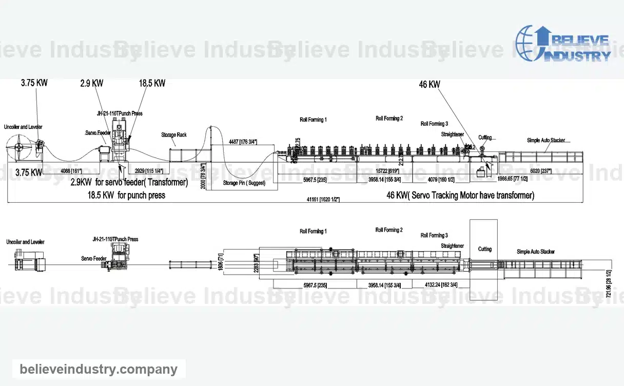
For roll forming machine installation, mark the centre line on the floor before anything is uncrated. The layout drawing gives the length of each module and the gaps between them. A 20 stand line with a punch press and a flying shear needs 18 to 24 m, plus coil loading space at the front and a clear run out at the back.

roll forming line layout drawing with stand positions

Check four things. Crane access over the uncoiler, 0.9 m of cabinet door swing, a hose route clear of the walkway, and a run out table longer than the longest part. Allow 3 to 4 m ahead of the uncoiler and 0.8 to 1.0 m of walkway along one side.

The mill base drawing sizes the heaviest module. If the floor cannot carry that point load, shimming at step three will not hold the setting.

Step 2: Concrete Foundation and Anchor Bolts

Most lines sit on a reinforced slab 200 to 300 mm thick, cast on compacted ground and isolated from columns that transmit vibration. That is a starting point, not a structural design. Thickness comes from machine mass, punch force and the soil report.

Anchor bolts go in before the machines arrive. Use the supplier bolt plan, not a guess based on the base plate you can see from outside. Check bolt centres after the concrete cures, because a 5 mm shift at the press feet is half a day of torch work later.

Foundation itemTypical starting valueOwner
Slab thickness200 to 300 mm reinforcedBuyer civil engineer
Concrete strengthC25 to C30 or local equivalentBuyer civil engineer
Anchor boltsM16 to M24, per bolt planSupplier drawing, buyer installs
Vibration isolationPads under press and hydraulic stationSupplier specifies
Floor flatness2 to 3 mm over 3 m before shimmingBuyer

Keep the cable trench and drainage channel out of the bolt grid. We have seen a trench cut through the anchor zone on delivery morning, which cost a new base plate and two weeks. Concrete detail belongs in its own guide; this step sets the acceptance point for roll forming machine installation.

Step 3: Positioning and Leveling

During roll forming machine installation, set the heaviest module first, usually the forming mill, then work outwards. Set each base plate on steel shims, not on wood or grout bags. Level across the machine and along the pass line with a machinist level or a laser.

roll forming machine base and forming stands

A working target for roll forming machine installation is 0.05 mm per metre across the stands and 0.10 mm per metre along the line. Those are setting targets, not a civil tolerance. Tighten anchor bolts in a cross pattern, then recheck the level. Torque always moves the reading on the first pass.

Grout only after the dry run, since grouting before alignment locks in the error. Isolate press feet from the mill base so press shock does not walk the mill out of level.

Step 4: Pass Line and Roll Alignment

The pass line is the horizontal centre line that strip follows from the leveler to the shear. Set it with a taut wire or laser through the first and last stand, then bring every intermediate stand to that line. Roll gap comes next, set at the entry and checked at the exit with the same feeler gauge.

In roll forming machine installation, work on alignment only after the base is level. The punching die installation guide covers die height and die centre, and the CZ purlin calibration guide gives a pass by pass sequence that transfers to other profiles. Both assume a flat base.

A short strip test tells you more than a dial gauge. Feed 2 to 3 m of the actual coil by hand through the first six stands. If the strip drifts to one side, the entry guides or one stand are out, not the coil. Fix that before powering the mill on any roll forming machine installation.

Step 5: Hydraulic, Air and Electrical Connections

Connect the hydraulic station to the punch, shear and uncoiler, then bleed each circuit. Check motor rotation before coupling anything. A pump running backwards for ten minutes does damage that no site schedule can absorb.

plc control cabinet on roll forming line

Every roll forming machine installation starts electrical work at the buyer isolator. Confirm voltage, phase and frequency against the nameplate, then check every emergency stop, guard switch and photo eye before the first powered motion. NEMA publishes enclosure and wiring guidance that helps when site rules differ from the machine build standard. The Fabricator has long running coverage of roll forming setup practice for the mechanical checks.

Fit the labelled quick disconnect plugs supplied with the line and record which cable went where. Label both ends. A roll forming machine installation that ships with unlabelled plugs costs a day at the next service visit.

Step 6: Dry Run Without Coil

For roll forming machine installation, run every station empty, one at a time, then all together. Cycle punch, shear and stacker for 30 minutes at low speed. Check oil temperature, hose movement and sensor lights. Confirm that emergency stops kill all motion, guards block startup, the encoder matches a measured stroke and pressure holds without drift.

Record the baseline numbers. They are the reference when a buyer calls six months later about a slow cut. The upright rack setup guide shows how those checks feed into the first good profile on a punched line.

Step 7: First Coil and First Good Profile

On the last day of roll forming machine installation, thread the first coil at the lowest line speed. Our published speed bands are 3 to 4 m/min for hydraulic stop cutting, 10 to 15 m/min for press cutting, 20 to 35 m/min for a flying saw and 30 m/min or more for rotary cutting. Start below the band, then move up one step at a time.

Measure the first part against the profile drawing, not against the sample on the quotation. Check width, height, lip angle, hole position, cut length and straightness. A bowed part at this point is an alignment problem, not a tooling problem.

Acceptance itemTypical toleranceWhere measured
Cut lengthplus or minus 1.0 to 1.5 mmFirst 10 parts
Hole positionplus or minus 0.5 mmPunched part
Profile widthplus or minus 0.5 mmCaliper at three points
Bow over 3 munder 2 mmStraightedge on run out table
Twist over 3 munder 1 degreeBoth ends on a flat table

Sign off only after 20 consecutive parts pass. The quality control and certificate page lists the factory checks before shipping, so the site check is the second half of the same record. That closes roll forming machine installation and hands the line to production.

Common Faults and What They Cost

FaultUsual causeSite fix
Strip drifts to one sideEntry guide or one stand off the pass lineReset wire line, adjust entry guides
Bow along the partUneven roll gap top to bottomRe set gap across all stands
Oval holesPunch die centre misalignedRe centre die, check strip flatness
Cut length wandersEncoder wheel slippingClean wheel, check coupling
Oil temperature climbsPump running backwards or relief set highCheck rotation, reset relief

Most of these trace back to steps two to four. That is why a roll forming machine installation crew should not be swapped mid job. The fitter who set the wire line should be the one who measures the first part.

What to Put in the Enquiry

Five items decide a roll forming machine installation plan and the quoted site days.

  • Line length and the longest part length, since they set the run out footprint
  • Floor condition, slab thickness and whether anchor bolts are already cast
  • Available crane capacity and ceiling height over the uncoiler
  • Site voltage, phase and frequency, plus who provides the isolator
  • Whether the supplier engineer is booked for commissioning and training

Ask for the bolt plan and layout drawing at order stage, not at shipping stage. The roll forming machine price guide covers the cost side of these choices, including the items buyers forget until the crate arrives.

Believe Industry has built custom roll forming lines since 2005, with 80+ engineers and 500+ projects in 50+ countries under ISO 9001 and CE. We send the foundation drawing with the order confirmation, because roll forming machine installation starts on the buyer floor weeks before our fitter gets on a plane.

Frequently Asked Questions

Q: How long does roll forming machine installation take?

A 15 to 25 m line takes 5 to 10 working days with two fitters, one electrician and a crane, once the slab has cured. Cassette lines add 1 to 2 days for changeover trials. Bad anchor bolt positions cost more time than any other fault.

Q: Can a roll forming line sit on an existing factory floor?

Often yes, if the slab is 200 to 300 mm reinforced and flat within 2 to 3 mm over 3 m. Check the mill base point load with a civil engineer. Chemical anchors are acceptable only where the bolt plan allows them.

Q: Who supplies the anchor bolts and the foundation drawing?

The supplier supplies the foundation drawing, bolt plan and footprints. The buyer supplies concrete, bolts and labour. Getting the bolt plan at order stage avoids recasting work.

Q: What level tolerance does the mill base need?

Use 0.05 mm per metre across the stands and 0.10 mm per metre along the pass line. Recheck after torquing bolts in a cross pattern. Grout after the dry run.

Q: Do we need the supplier engineer on site?

For the first line, yes. Steps four to seven need someone who has set that roll pass before. Remote support works for later lines of the same profile.

Q: What is checked before the first coil is threaded?

Motor rotation, emergency stops, guard switches, pressure holding for 30 minutes, punch timing and the cut length encoder. Then all stations cycle together empty.

Last updated: 2026-11-05

Article Changelog

2026-11-05: Initial publication in the 2026-11-05 calendar slot, backfilled on 2026-11-14.

Next Review Triggers

Anchor bolt plan or base plate design changes on a shipped line; site wiring rules or enclosure ratings change; a buyer asks to install on a slab under 200 mm; first run tolerance targets move.

Table of Contents

New Updates