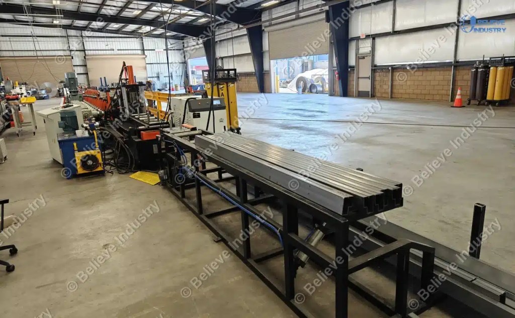
Step beam roll forming machine forming line and run out table

Step Beam End Processing: 6 Cutout and Hole Rules 2026

Need a Roll Forming Machine for Your Project?
Get a free quote from Believe Industry — 15+ years of custom roll forming manufacturing.
Request a Quote Download Catalogue

Step Beam End Processing: 6 Rules for Cutouts, Notches and Connection Holes

Short answer: Step beam end processing is the punching, notching, cutting and welding work that turns a formed rack beam into a part that locks into an upright. Six rules decide the result. Freeze the connector drawing first, punch holes on flat strip, hold the datum to the cut end, size the notch to beam depth, pick the cut method by burr limit, and weld the end clips in a fixture. Most field complaints trace back to hole position rather than beam strength.

A rack beam carries the load in the middle. Step beam end processing decides what happens at the ends. The connector, the hook pattern and the cut face decide whether the beam drops into the upright or jams on site. Step beam end processing covers the last 150 to 250 mm of the part, and that short length drives most of the tooling cost.

This guide stays on step beam end processing. For the full route from coil to finished beam, see the step beam production process. For thick coil forming, see heavy duty step beam roll forming. Neither replaces the profile drawing that comes with the tooling order.

What Step Beam End Processing Covers

A finished beam end has four jobs. It has holes that take the connector hooks or bolts. It has a notch or relief that clears the upright face. It has a square cut face at the right length. It has an end clip welded in the right plane so the hooks engage together. Step beam end processing delivers all four in a repeatable order.

Step beam end processing sits on the same roll forming machine line as the forming mill, but it uses different stations. A pre punch unit sits before the first forming stand. A cut unit sits after the last stand. A weld fixture sits off line or at the run out table. The step beam roll forming machine is the whole chain; the end process is the tooling at both ends of it.

Step beam end processing does not include the upright hole pattern, the powder coat line or the rack design calculation. Those belong to the rack engineer. MHI standards are a useful reference for the rack side of the boundary.

The Six Rules In One Table

RuleWhat to fixTypical shop targetFailure if ignored
1Connector drawing and hook patternFrozen before die cuttingNew clips do not fit old beams
2Punch position on flat stripHole to end within 0.5 mmHoles drift after forming
3Datum at the cut faceEncoder referenced to cut, not coil edgeCumulative feed error at long lengths
4Notch size by beam depthRoot radius kept, no sharp cornerCracks start at the notch root
5Cut method by burr limitBurr under 0.2 mm after deburrHooks hang up, hands get cut
6End clip welded in a fixtureClip square within 0.5 mmOne hook carries all the load

These are shop targets for step beam end processing, not a rack code. Confirm them against the beam drawing and the connector supplier sheet before they go into a purchase order.

Rule 1: Freeze the Connector Drawing Before Tooling

The connector decides the holes. A three hook clip, a four hook clip and a bolted end plate each need a different hole pattern, a different edge distance and a different safety lock position. Step beam end processing starts with that drawing, not with the coil.

Upright hole pitch matters to step beam end processing too. A 50 mm pitch and a 75 mm pitch call for different hook spacing. Ask the rack designer which upright the beam will meet, then pass the upright rack roll forming machine profile drawing to the tooling shop at the same time. Changing the connector after the die is cut means buying a new die and a new weld fixture.

step beam line decoiler and hydraulic punching unit

Rule 2: Punch on Flat Strip, Not After Forming

A step beam is a closed or near closed section. Once the two flanges are rolled together, a conventional die cannot reach the inside face. That is why step beam end processing puts the punch unit before the first stand, while the strip is still flat.

In step beam end processing, a hydraulic punch with servo feed stops the strip, fires the die and indexes to the next position. A rotary or travelling punch keeps the strip moving. Both need a clean die, correct clearance and a strip that is flat enough to sit on the die face. The punching die installation guide covers clearance and alignment; upright rack punching faults covers the drift symptoms that appear later.

StationPlacementTypical line speedWhat it controls
Decoiler and straightenerLine entry15 to 25 m/minStrip flatness at the die
Hydraulic pre punchBefore stand 13 to 4 m/min stop and goHole pattern and hole to end distance
Servo travelling punchBefore stand 110 to 15 m/minHole pattern without stopping
Forming mill20 to 28 stands10 to 20 m/minSection shape and step height
Flying saw or shear cutAfter last stand20 to 35 m/minLength, end squareness, burr
Auto stackerRun out15 to 25 m/minBundle order and surface damage

The slowest station sets the line pace. A stop and go punch can halve the output of an otherwise fast mill.

Rule 3: Hold the Datum to the Cut End

Servo feed accumulates small errors over a long beam. If the hole pattern is measured from the coil edge, a 3 m beam and a 2.7 m beam from the same coil will show different hole to end distances. Step beam end processing should measure from the cut face.

In practice the encoder counts from the punch, the cut fires at a set count and the control compensates for blade position. Ask for a 30 piece sample with hole to end distance recorded on each piece. A drifting number means the datum is on the wrong end of the line.

Rule 4: Size the Notch to Beam Depth and Wall

The end notch clears the upright column and the adjacent beam. Cut too little and the beam will not seat. Cut too much and the hook zone loses material. Step beam end processing has to balance both against beam depth and strip thickness.

Common rack beams run 1.5 to 3.0 mm wall. A sharp notch root becomes a crack starter under cyclic pallet loading, so ask for a rounded root and keep the notch one hole diameter away from the hook holes. The fabricator reference library covers notch behaviour in formed sheet. Heavy duty beams need the relief checked against the actual connector.

Rule 5: Choose the Cut by Burr and Squareness

Two cut methods dominate step beam end processing. A flying saw tracks the moving beam, clamps and cuts with a rotating blade. It suits closed sections and runs at 20 to 35 m/min. It leaves saw swarf and a burr that needs a deburr pass. A hydraulic shear or cut off die is faster per cut, gives a squarer face and can collapse a closed corner if the blade is worn.

step beam cut off unit and run out table

Step beam end processing has to state the burr limit at the hook slots. A burr inside a slot stops the clip from seating. Blade life belongs in the spare parts list, and the quality control record should include the cut face check. NEMA guidance covers the electrical side of the cut drive.

FeatureShop targetHow it is measuredWhy it matters
Hole to end distanceWithin 0.5 mmCalliper from cut faceClip engagement
Hole pitch across the endWithin 0.3 mmGauge or vision checkAll hooks share the load
Cut lengthWithin 1.0 mmTape against beam drawingRack bay fit
End squarenessWithin 0.5 mm over section depthSquare on cut faceBeam sits flush to upright
Clip squarenessWithin 0.5 mmFixture gauge after weldNo twist in the connection
Burr height after deburrUnder 0.2 mmRun a fingernail or gaugeSafe handling, clean seating

Rule 6: Weld the End Clips in a Fixture

Step beam end processing welds the end clip after the beam is cut. A double station welder handles both ends of a beam in one cycle, but only if the beam is held square in a fixture. Free hand welding gives a clip that looks right and loads wrong. The line ends at that fixture, not at the cut unit.

double working station automatic welder for step beam and end clips

Check three things on the first article: every hook enters the upright slot together, the safety lock hole lines up, and the clip face sits flat. Pull a sample from each shift for a load check. Weld spatter in a hook slot is a rejection.

Common Faults and What Causes Them

SymptomLikely causeFix
Clip will not enter uprightHook pitch or hole driftRecheck datum and punch die
Beam sits high on one endClip welded out of squareRebuild weld fixture stop
Crack at notch rootSharp corner or over cutAdd root radius, reduce relief
Burr inside hook slotWorn blade, no deburrChange blade, add deburr station
Hole pattern walks along a coilEncoder slip or feed roll slipClean rolls, reset compensation
Corner collapsed at cut faceShear blade worn on closed sectionSwitch to saw or renew blade

Step beam end processing faults are cheap to fix at the line and expensive to fix on a rack with pallets on it. Ask for a first article report before the container is packed.

Speed, Tooling and What Drives the Quote

Line output in step beam end processing follows the punch. A stop and go hydraulic punch caps a line near 3 to 4 m/min regardless of how fast the mill can roll. A travelling punch lifts that band to 10 to 15 m/min and adds to the price. The roll forming machine price guide breaks down where that money goes. An auto stacker matters more than it looks, since a dropped bundle damages the cut faces that were just measured.

For a step beam end processing quote, send the connector drawing, upright hole pitch, beam length list, wall thickness range, daily output and inspection sheet with the enquiry. Two beam depths can share a mill, but they rarely share a punch die and a weld fixture. Ask the supplier to quote those as separate line items.

How This Differs From Upright and Box Beam Work

An upright column is punched along its full length, so its line lives or dies by feed accuracy over metres of strip. A step beam is punched at both ends only, so step beam end processing lives or dies by cut referenced position. That is why a good upright line does not automatically make good beam ends.

A box beam machine uses roughly 14 forming stands plus 5 seam stations and usually ends with a flat cut and an end plate. It has no hook pattern, and borrowing its end tooling is a costly shortcut.

Frequently Asked Questions

Q: Can we punch holes after the beam is formed?

On a closed step beam, no. The die cannot reach the inside face. Punch on flat strip before the first forming stand, or design a special side acting unit at much higher cost.

Q: Which cut is better for a closed section?

A flying saw keeps the section shape and leaves a burr to deburr. A shear gives a squarer face but can collapse a closed corner. Choose by burr limit at the hook slots, not by cycle time alone.

Q: How many hooks should an end clip have?

It follows the rack design and the upright hole pitch. Three and four hook clips are both common. Freeze that drawing before the punch die is cut, since the hook count sets the hole pattern.

Q: What tolerance should we ask for on hole to end distance?

A practical shop target is within 0.5 mm measured from the cut face. Ask for a 30 piece sample with each value recorded, not a single first article measurement.

Q: Do we need a separate end clip welder?

Yes for most racking lines. Step beam end processing is not complete without a controlled weld. A double station fixture welds both ends and holds clip squareness. Welding at the run out table without a fixture gives inconsistent connections.

Q: Can one line run two beam depths?

The forming mill often can, with a roll change or a cassette. The punch die and weld fixture usually cannot. Quote them as separate tooling for each depth.

Last updated: 2026-11-09

Article Changelog

2026-11-09: Initial publication in the 2026-11-09 calendar slot, backfilled on 2026-11-15.

Next Review Triggers

Connector drawing or upright hole pitch changes; a buyer asks for a new beam depth; cut method changes from saw to shear; inspection targets move.

Table of Contents

New Updates