Address
No 1, Yd Road, Huishan District, Wuxi City, Jiangsu. 214183
Work Hours
Monday to Friday: 9AM - 5PM
Saturday: 9AM - 4PM

Every roll forming project starts with a coil. Before you cut a single roll station or design a flower pattern, you need the exact coil width. Get it wrong and you waste steel, distort the profile, or scrap the entire batch. Get it right and your material yield stays high, your edges stay clean, and your machine runs at full speed.
Coil width calculation for roll forming is not guesswork. It is a precise engineering exercise based on profile geometry, bend allowance, and trim allowance. Believe Industry Company has been configuring roll forming lines for over 15 years, shipping to 20+ countries. We have seen every coil width mistake in the book. This guide walks through the five most important factors that determine your coil width and thickness selection.
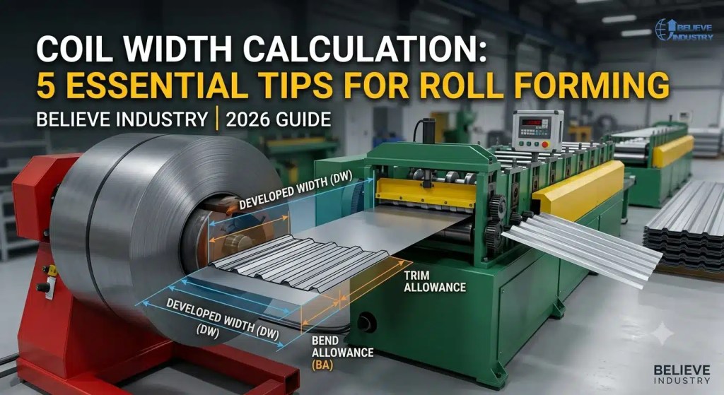
Coil width calculation is the process of determining the flat strip width needed to produce a specific roll-formed profile. The profile you see on the exit side of the machine started as a flat strip on the entry side. The width of that strip determines everything downstream.
The basic concept is simple. You take the profile cross-section, unfold each bend back to flat, and add up the total flat width. That total is your profile developed width. Then you add trim allowance for edge conditioning and shearing. The result is the coil width you order from the steel mill.
But the execution has nuance. Bend allowance changes with material thickness, bend radius, and material yield strength. A profile drawn on paper at 100mm cover width might need 108mm or 112mm of coil depending on those variables. The roll forming machine line must be designed around the correct coil width from day one. A cable tray roll forming machine built for 300mm tray width needs a different coil spec than one built for 150mm trays. The calculation comes first, the machine design follows.
Profile developed width is the flat length of material required to form the final cross-section. Think of it as unrolling the profile back to its original flat state. Each leg, each web, and each bend contributes to the total.
To calculate developed width, you need the profile drawing with all dimensions. You measure each flat segment. Then you calculate the bend allowance for each formed corner. The sum of all flat segments plus all bend allowances equals the developed width.
For example, a simple U-channel with a 40mm base and two 20mm legs at 90 degrees looks like it needs 80mm of material. But each 90-degree bend consumes material through the bend radius. The actual developed width might be 84mm or 86mm depending on the inside radius and material thickness. Getting this number right is step one of any coil width calculation.
Engineers use profile width calculation software like COPRA or dataM to automate this process for complex profiles. A standing seam roll forming machine profile with multiple legs and return bends can have 8 to 12 formed corners. Manual calculation for that many bends invites errors. Software handles it in seconds. But you still need to understand the math behind the software to verify its output.
Bend allowance is the length of material consumed in a bend. When flat strip passes through roll stations and forms an angle, the material stretches on the outside and compresses on the inside. The neutral axis, somewhere between the two, stays the same length. Bend allowance calculates the arc length of that neutral axis.
The standard width formula for bend allowance is:
BA = (pi / 180) x A x (R + K x T)
Where:
The K-factor is where experience matters. For thin material (0.3 to 0.8mm), a K-factor of 0.33 is common. For thicker structural material (2.0 to 4.0mm), 0.40 to 0.45 works better. High-strength steel with elevated yield strength may need a different K-factor entirely. The American Iron and Steel Institute provides reference data for K-factors by steel grade and temper.
A wrong K-factor means a wrong bend allowance. A wrong bend allowance means a wrong developed width. And a wrong developed width means you ordered the wrong coil width. The error cascades through the entire production chain. A metal roof tile roll forming machine profile with 6 bends and a 0.02mm K-factor error can shift the total developed width by 3 to 5mm. That is enough to cause edge wave or profile distortion in the finished panel.
Trim waste is the material trimmed off the edges of the strip during or after forming. Most roll forming lines include edge trimming to ensure clean, consistent edges on the finished profile. This trim is not optional. Without it, slit-edge variation from the mill shows up as wavy or inconsistent profile edges.
Standard trim allowance is 3 to 7mm per side, depending on the slitting quality of your incoming coil. Mill-supplied coil with factory-cut edges needs less trim. Slit-to-width coil from a service center may need more. A corrugated sheet roll forming machine typically trims 5mm per side on a 914mm coil to achieve a clean 904mm cover width.
Your total coil width formula is:
Coil Width = Developed Width + (2 x Trim Allowance)
Some profiles need more trim. Pre-painted material with decorative finishes requires wider trim to avoid paint cracking at the slit edge. Structural profiles like pallet racking uprights may skip trimming entirely if the profile tolerances allow it. The coil spec should document your trim strategy clearly. When a double layer roll forming machine runs two profiles from the same coil, the trim strategy must account for both profile geometries.
Thickness selection drives every other decision in the roll forming process. The material thickness determines roll station count, drive motor sizing, cutoff force, and the bend allowance itself. Choose the wrong thickness and the entire coil calculation falls apart.
Common thickness ranges by application:
| Application | Thickness Range | Typical Profile |
|---|---|---|
| Roofing and wall cladding | 0.3 to 0.8 mm | Corrugated, IBR, standing seam |
| Drywall studs and tracks | 0.4 to 2.0 mm | C-stud, U-track |
| Strut channel | 1.5 to 3.0 mm | P1000, C-channel |
| Pallet racking | 1.5 to 4.0 mm | Upright, box beam |
| Elevator guide rails | 2.0 to 6.0 mm | T-rail, hollow guide |
Thickness also affects material yield. Thicker steel costs more per meter but delivers higher structural capacity. A standing seam roof panel running 0.5mm coil produces more linear meters per ton than the same machine running 0.8mm coil. Your thickness selection should match the structural requirement without over-specifying. The ASTM International standards database defines thickness tolerances for hot-rolled, cold-rolled, and coated steel coil used in roll forming.
An IBR sheet roll forming machine running 0.47mm BMT (base metal thickness) meets South African SANS 994 requirements for residential roofing. The same profile at 0.8mm BMT serves industrial warehouse applications. Same profile geometry, same developed width formula, but different thickness selection changes the coil spec and the machine configuration.
Coil optimization is about getting the most finished product from each ton of steel. Every millimeter of trim waste and every miscalculated bend allowance eats into your material yield. Over a year of production, small errors add up to tons of wasted steel.
Three practices drive coil optimization:
1. Order coil slit to your exact developed width plus trim. Standard mill widths like 914mm, 1000mm, and 1250mm are convenient but rarely match your profile. Custom slit widths eliminate the need to trim excess material. A manufacturer running a C-strut roll forming machine for P1000 channel (41x41mm) needs roughly 105mm developed width. Ordering 112mm slit-to-width coil instead of cutting from 1250mm standard saves 8 to 10% on material cost per linear meter.
2. Nest profiles to share coil width. If you produce multiple profiles, check whether two can share the same coil width. A 200mm coil might serve both a 92mm drywall stud and a 150mm track if the developed widths are close. Profile nesting reduces coil inventory and simplifies ordering. The trade-off is slightly more trim waste on the narrower profile, but the inventory savings often outweigh the material loss.
3. Track coil usage with digital monitoring. Modern PLC systems log coil consumption per shift, per profile, and per production run. This data reveals waste patterns invisible to manual tracking. A roll forming machine line with integrated coil tracking can flag a 2% yield drop in real time. The GalvInfo Center offers guidance on coil edge quality and its impact on material yield for galvanized and Galvalume coated steel.
| Parameter | Coil Width | Material Thickness |
|---|---|---|
| What it determines | Profile coverage width, edge quality | Roll station count, drive power |
| Calculation basis | Developed width + bend allowance + trim | Structural requirement + standard availability |
| Typical tolerance | plus or minus 0.5 mm | plus or minus 0.02 mm |
| Impact of error | Scrap, edge wave, profile distortion | Roll damage, motor overload, springback |
| Optimization lever | Custom slit width, profile nesting | Match to structural spec, avoid over-spec |
Ignoring springback in bend allowance. High-strength steel springs back more than mild steel. If you calculate bend allowance for mild steel but run high-strength coil, your developed width is wrong. Add 1 to 2% extra material for high-strength profiles to compensate for springback.
Using paper dimensions without K-factor. A profile drawing shows the finished dimensions. It does not show the neutral axis position. Without the correct K-factor, your bend allowance is an estimate, not a calculation. Always verify the K-factor with a test sample before committing to a coil order.
Forgetting trim on pre-painted coil. Painted coil cracks at slit edges during forming. You need 5 to 7mm of trim per side to remove the cracked edge. Skip the trim and your profile edges look rough and fail inspection. This is one of the most common coil spec errors we see.
Ordering standard widths instead of custom slit. A 1000mm coil for a profile that needs 960mm developed width wastes 40mm per linear meter. Over a 5-ton coil, that is 200 meters of wasted steel. Custom slit widths cost slightly more per kilogram but save far more in yield. Coil usage tracking makes this waste visible and quantifiable.
Every roll forming line we build starts with a profile drawing. Our engineers calculate the developed width, apply the correct bend allowance for the specified material, and add trim allowance based on the incoming coil condition. We then specify the exact coil width on the machine data sheet.
This process has been refined over 15 years and across 20+ countries. We have configured lines for metal roof tile profiles in Europe, IBR sheet profiles in South Africa, and C-strut channels in North America. Each market has different standard coil widths, different material grades, and different trim expectations. The coil width calculation adapts to all of them.
We provide a complete coil spec sheet with every machine. It lists the developed width, bend allowance per corner, K-factor used, trim allowance, and final coil width recommendation. Our customers can hand this sheet directly to their steel supplier. No guesswork, no trial and error on the production floor.
Developed width is the flat material length needed to form the profile, calculated from the profile geometry and bend allowance. Coil width is the actual strip width you order from the mill, which equals developed width plus trim allowance on both edges.
Use the formula BA = (pi / 180) x A x (R + K x T), where A is the bend angle in degrees, R is the inside bend radius, K is the K-factor (0.33 to 0.45 for most roll forming), and T is material thickness. Sum the bend allowances for all corners in the profile cross-section.
Start with 0.40 for high-strength steel with yield strength above 350 MPa and verify with a test sample. High-strength material shifts the neutral axis outward, increasing the K-factor compared to mild steel where 0.33 is standard.
Standard trim is 3 to 5mm per side for mill-edge coil. For slit-to-width coil from a service center, use 5 to 7mm. Pre-painted coil needs 5 to 7mm minimum to remove paint cracking at the slit edge. Always document the trim strategy in your coil spec.
Yes, if the developed widths are close enough to share a single slit width. This is called profile nesting. It reduces coil inventory and simplifies ordering. The trade-off is slightly more trim waste on the narrower profile, but the inventory savings usually outweigh the material loss.
Thickness enters the bend allowance formula directly through the T variable. Thicker material means a larger bend allowance for the same angle and radius. A profile at 0.5mm and the same profile at 1.0mm will have different developed widths even if the finished dimensions look identical.
Plus or minus 0.5mm for slit-to-width coil. Plus or minus 2mm for mill-edge coil. Tight tolerances matter for profiles with narrow edge margins or precise cover widths. Your coil spec should state the required tolerance class.
Track coil consumption per profile using your PLC system. Identify profiles with similar developed widths and consolidate them to shared coil widths. Order custom slit widths instead of standard mill sizes. Review your coil optimization strategy quarterly to catch drift in material yield.
Last updated: August 4, 2026
Article Changelog:
Next Review Triggers:
Every roll forming project starts with a coil. Before you...
Read MoreEvery factory owner buying roll forming equipment hits the same...
Read MoreMost roll forming lines run one profile. That is the...
Read MoreIntroduction A wall cladding roll forming machine takes flat steel...
Read MoreSubscribe now to keep reading and get access to the full archive.