Home / Roll Forming Machine / Customized Profile Roll Forming Machine / Perforated Cable Tray Production Line

Perforated Cable Tray Production Line

How a Perforated Cable Tray Production Line Works

Short answer: A perforated cable tray production line uncoils steel strip, punches the hole pattern while the strip is still flat, forms the C section through 22 roll stands, and cuts to length. Our standard build runs 0.6 to 2.0 mm steel, 50 to 600 mm tray widths, and 10 to 15 m/min behind a 110 t press.
Three decisions shape the machine. Where the holes get punched, how many stands carry the bends, and how the operator changes width. Get those right and the line runs for fifteen years. Get one wrong and every new order turns into a fight with scrap.
This page covers the layout, the spec sheet, the three punching routes and the output math that decides payback. For the product itself, our guide to what a cable tray is covers types, load classes and finishes.
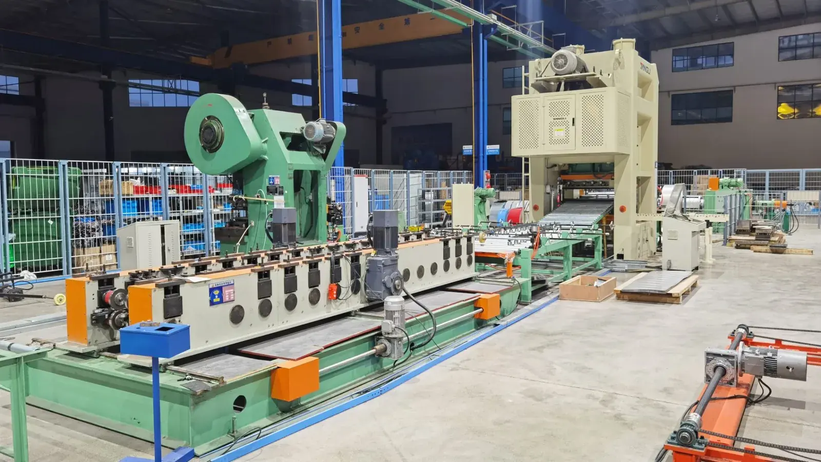
Cable tray roll forming machine production line with punching press and roll former in factory

What a Perforated Cable Tray Production Line Produces

The perforated cable tray production line makes a C section with a punched bottom and punched side walls. Four numbers define that section, and all four move together.
  • Width, 50 to 600 mm, measured outside the side walls
  • Side height, 50 to 100 mm
  • Return flange, usually 15 to 25 mm, which stiffens the top edge
  • Material thickness, 0.6 to 2.0 mm
On a perforated cable tray production line, holes are punched before forming, while the strip is still flat. A typical tray uses 6 x 30 mm or 8 x 35 mm slots on a 25 mm pitch, with matching slots in the side walls for the coupler. The pattern lives in the punch die. The profile lives in the roll set. A new perforation therefore does not mean new rolls.
Tray widthSide heightThicknessTypical useStrip width needed
50 to 100 mm50 mm0.6 to 1.2 mmInstrument and control cable240 to 290 mm
150 to 300 mm50 to 75 mm0.8 to 1.5 mmCommercial power distribution290 to 490 mm
400 to 500 mm75 to 100 mm1.0 to 2.0 mmData centre and plant rooms640 to 780 mm
600 mm100 mm1.2 to 2.0 mmHeavy runs and trunking840 mm
Read the last column before you price a coil. Strip width is what you buy, tray width is what you sell, and the gap becomes two side walls and two return flanges. A 600 mm tray takes 840 mm of strip, so roughly 28 percent of the coil never appears as tray bottom. The mill takes strip to 1100 mm, which lets one frame run tray, cover and Russian type profiles.

Six Stations on a Perforated Cable Tray Production Line

Every perforated cable tray production line follows the same order. The stand count changes with the profile. The order does not.
  • Decoiler. 6 t hydraulic, 508 mm inner diameter, 1200 mm outer, 4 kW motor with integral reducer. A manual mandrel is the cheaper option.
  • Leveler. 11 rolls, four over five plus two clamp delivery rolls, 5.5 kW, ZQ250 reducer, rated to 2.0 mm at 1000 mm width.
  • Servo feed and press. 3 kW feeder into a 110 t mechanical press at 60 to 90 strokes per minute, with a fixed 50 s.p.m mode.
  • Roll forming mill. 22 stands, 85 mm shafts, GCr15 rolls at HRC 58 to 62, 30 kW inverter motor and ZQ500 main reducer.
  • Cut-off. Hydraulic shear with Cr12MoV blade, length keyed on the touch screen, held to plus or minus 1 mm on a 3 m tray.
  • Run-out table. Two angle steel tables, with an automatic stacker added above 15 m/min.
Russian type cable tray production line
The leveler earns its place more than its price suggests on a perforated cable tray production line. A strip carrying coil set enters the die at an angle, and the pattern walks off centre over a 300 m run. Level first, punch second, form last. Our decoiler types guide covers when a hydraulic mandrel pays for itself.

Where the Line Punches: Three Routes

Hole position is the biggest layout decision on a perforated cable tray production line. Three routes exist, and each fits a different order book.
RouteHow it worksFits bestWatch out for
Inline pre-punchPress sits between leveler and mill and punches the flat stripMost perforated tray, one repeating patternHoles deform slightly in forming, so the die must be compensated
Post-punchFormed section passes through a second pressHoles that must stay true after bendingTooling access inside a C section is tight
Rotary punchPunch rings on a roll hit while the strip movesLong runs, single pattern, high speedPattern change needs new rings
Pre-punch covers about nine out of ten orders. The die is drawn oversize along the forming direction, so a slot that starts oval arrives round at the cut-off. Ask the tooling engineer for the compensation drawing, not only the finished pattern. Setting practice sits in our guide to punching die installation.
Post-punch suits a factory that also sells solid tray, because the mill can run with the press idle. It costs a second press and more floor length. Rotary punch is the fastest of the three and the least flexible, so it belongs to factories running one pattern for years.

Technical Parameters

The figures below describe our standard perforated cable tray production line. Treat them as a starting envelope, not a fixed product.
ItemUnitValue
Yield strength of coilMPa235 to 400
Coil thicknessmm0.6 to 2.0
Strip widthmm100 to 1100
Tray widthmm50 to 600
Tray side heightmm50 to 100
Line speedm/min10 to 15
Forming standssets22
Shaft diametermm85
Roller materialGCr15, quenched to HRC 58 to 62
Main drivekW30, inverter motor with ZQ500 reducer
Punching presst110, 60 to 90 strokes per minute
Servo feederkW3, line speed to 200 m/min
Hydraulic decoilert6, 508 mm ID, 1200 mm OD
Total connected powerkW75
Floor spacem55 x 4 x 3.5
ControlPLC, touch screen, encoder length control, Panasonic or Siemens
A line built for 600 mm tray at 2.0 mm carries a heavier frame and a larger press than one built for 300 mm at 1.0 mm. Our cable tray line cost guide shows how each choice moves the price.

Why a Perforated Cable Tray Production Line Needs 22 Stands

A C section on a perforated cable tray production line carries four bends: two bottom corners and two return flanges. Each bend is spread over several stands, and the roll designer decides how it is divided. The gauge sets the limit.
A 0.6 mm strip takes a 25 degree bite per stand without marking. A 2.0 mm strip wants 12 to 15 degrees, or the outside fibre stretches past yield and the corner cracks at the next bend. That rule explains why one frame needs more stands to cover 0.6 to 2.0 mm than to cover 1.2 mm only.
22 stands holds the whole range. Fewer stands make a cheaper machine that struggles above 1.5 mm. Springback rises with yield strength too, so a buyer running 400 MPa strip at 2.0 mm should expect the calibration stands on a perforated cable tray production line to do real work.

Width Change Without a Roll Change

Width changes far more often than profile on a perforated cable tray production line. Telescopic shafts handle it, and they separate a factory that quotes fast from one that turns work away.
On telescopic shafts the side wall rolls slide and lock at the new width, while the bottom rolls stay put because a tray bottom is flat at every width. Two fitters reset the mill in 15 to 30 minutes. A fixed width mill needs six to eight hours for a full roll change.
Above three or four widths a week, look at a powered automatic size change cable tray machine, where positions are stored in the PLC and the reset runs from the touch screen.

Steel, Coating and Standards

Most perforated cable tray production lines run DX51D+Z, S250GD or S350GD galvanized coil. Stainless 304 appears in food plants and on coastal sites, aluminium on rail projects where weight is the constraint.
Yield strength between 235 and 400 MPa keeps the mill happy. Above 400 MPa springback rises, the mill needs more drive power, and straightness becomes a calibration problem rather than a forming problem.
Finish decides the coating line on a perforated cable tray production line, not the roll former. Pre-galvanized Z275 suits indoor runs. Hot dip galvanizing to ISO 1461 adds 65 microns and covers cut edges, which matters because every punched hole on a perforated cable tray production line is a bare edge.
Read the load table and the finish schedule together. NEMA VE 1 sets load classes for the US market and IEC 61537 covers most export destinations. CSA C22.2 No. 126 applies in Canada. A tray that passes one is not automatically compliant with another.

Output Math: Where the Line Bottlenecks

Mill speed is the headline number. The press window and coil changes set real output on a perforated cable tray production line.
Tray lengthPieces per hour at 10 m/minAt 15 m/min8 hour shift at 12 m/min, 75 percent OEE
2.0 m3004502,160
2.5 m2403601,730
3.0 m2003001,440
6.0 m100150720
The press is the first place to check on any perforated cable tray production line. One stroke punches a window of the pattern, so metres per minute equals window length times strokes per minute. At 70 strokes per minute a 300 mm window frees 21 m/min and the press never limits the mill. A 100 mm window frees only 7 m/min, and the press becomes the ceiling whatever the mill is rated at.
Coil changes are the second limit. A 6 t coil at 600 mm by 0.8 mm holds about 1,590 m, which is 133 minutes at 12 m/min. Each change costs 5 to 10 minutes, so four coils a shift lose half an hour at the decoiler. That is the case for a double mandrel, and for line speed optimization rather than a bigger motor.

Before You Sign: Six Checks

Six questions separate a perforated cable tray production line that fits from one that becomes a spare parts problem.
  1. Does the drawing show strip width for each tray width, or only the tray size?
  2. Is the press window matched to the hole pattern, or sized to the machine frame?
  3. Does the mill have the stands to hold your heaviest gauge?
  4. Is the return flange formed in the mill, or cut and bent in a second operation?
  5. Which standard does the load table follow, and does the finish schedule match it?
  6. Is the width change stored in the PLC, or does a fitter reset every stand by hand?
Believe Industry has built custom roll forming lines since 2005, with 80+ engineers and technicians, 500+ machines in 50+ countries under ISO 9001 and CE. We size the frame, rolls and press to your profile, the same discipline described in our custom profile roll forming engineering guide.
Send the tray drawing, the hole pattern and the target output to enquiry@believeindustry.com or use the request a quote form. Every perforated cable tray production line we quote starts from your drawing, not a catalogue, and we reply with a layout, the strip width calculation and a price within two working days.

Photo Gallery

Frequently Asked Questions

Q: What is a perforated cable tray production line?

A: A continuous line that turns steel coil into punched, formed and cut tray. Decoiler, leveler, servo feed, press, 22 stand mill and shear run in sequence, so one operator feeds coil at one end and stacks tray at the other.

Q: What thickness can the line punch and form?

A: 0.6 to 2.0 mm on the standard build, though most tray runs 0.8 to 1.5 mm. Pushing 2.0 mm at 600 mm width needs the heavier frame and a bigger press window, so state the maximum in the enquiry.

Q: Can I change tray width without changing rolls?

A: Yes, on a perforated cable tray production line with telescopic shafts. The side wall rolls slide and lock at the new width in 15 to 30 minutes, while a fixed width mill takes six to eight hours for a full roll change.

Q: Should holes be punched before or after forming?

A: Before forming for most orders. The flat strip is easier to punch, the die can be compensated for stretch at each bend, and the press sits in the same line. Post-punch suits buyers who also run solid tray.

Q: How fast does a perforated cable tray production line run?

A: 10 to 15 m/min. The press window and coil changes decide output, not the mill rating. A 3 m tray at 12 m/min gives about 1,440 pieces per 8 hour shift at 75 percent efficiency.

Q: What strip width do I need for a 400 mm tray?

A: Around 640 mm at 75 mm side height with a 20 mm return flange. Add the flanges and side walls to the bottom width, then confirm on the roll drawing, because bend allowance moves the figure by a few millimetres.

Q: Which standards apply to cable tray?

A: NEMA VE 1 in the US, IEC 61537 in most export markets, CSA C22.2 No. 126 in Canada. Load classes are defined differently in each, so approval for one market does not carry to another.

Q: How long is delivery and installation?

A: 45 to 60 days after drawing approval, plus time for a second press or powered size change. Installation, commissioning and training take 7 to 10 days on site with one engineer, and the line needs 55 m of floor length ready.
Last updated: 2026-11-01
Article Changelog
2026-11-01: Full rewrite of page 3088. Replaced the 2018 copy, moved the specification into three tables, reconciled the conflicting figures between the intro and the old parameter table, removed a duplicated closing paragraph, added the punching route comparison, output math, standards and eight FAQs.
Next Review Triggers
Tray load class definitions change in NEMA VE 1 or IEC 61537
Galvanized coil price moves more than 15 percent
New punching or size change tooling released for this line

Quick Inquiry

Send us your requirement — we'll reply within 24 hours.

Click or drag files here
PDF, DWG, DXF, STEP, PNG, JPG — Max 20MB

Inquiry Sent Successfully!

Thank you for your interest in Believe Industry.
Our engineering team will get back to you within 24 hours.

Need urgent response? Email enquiry@believeindustry.com

Table of Contents

Latest Posts Believe Industry

Buying Guider & Machinery Technology & Maintainence Tips