roll forming machine design

Roll Forming Machine Design

Roll forming machine design is the engineering plan for bending a flat metal strip into a finished cross-section. The strip passes through a series of contoured roller pairs, and each pair makes one small bend. A good plan uses the fewest rollers possible while still producing perfect parts on every pass. A bad plan shows up fast: warped edges, twisted profiles, or a machine that costs too much to run.

Two rules sit at the heart of every design decision. If the metal moves too fast through sharp bends, the part warps. If it moves too slowly through too many rollers, the machine wastes money. The sweet spot between those two limits is where good roll forming machine design lives.

Engineers at Believe Industry have built custom machines for over 15 years, and the same five rules drive every project. Before we dig in, it helps to know how the full roll forming machine works and why this process beats stamping for long profiles.

Cold Roll Forming

What Is Roll Forming Machine Design?

Roll forming machine design is the complete specification of every forming station, roller contour, shaft, and drive component needed to turn a flat coil into a repeatable profile. It starts with the part drawing and ends with a tooling package that holds tolerance run after run. In practice, the design phase decides roughly 80% of the final machine cost, because tooling mistakes are the most expensive mistakes to fix.

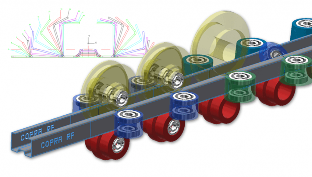
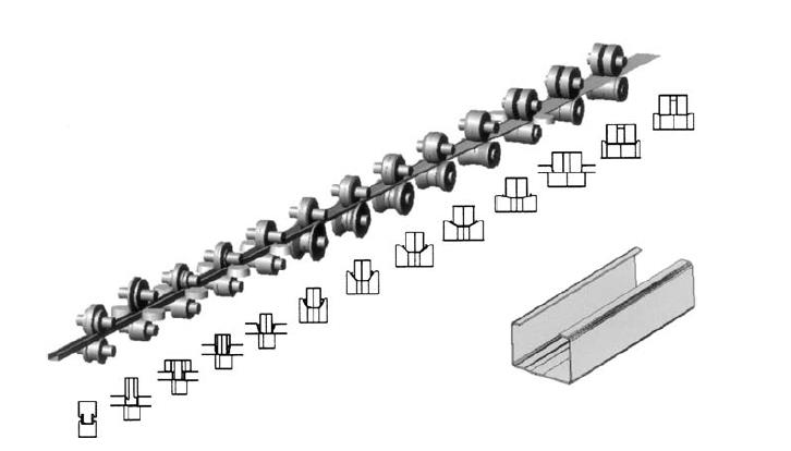
The classic tool for this work is the flower pattern. Engineers draw the flat strip, then overlay each bending step in sequence. The result looks like a flower opening, and it shows exactly where the strip stretches, where it compresses, and where trouble will appear. The technique is the industry standard documented in George T. Halmos’s Roll Forming Handbook, the reference most tooling engineers keep on their desks. If you want the full context on how profiles form step by step, read the guide to the roll forming process.

5 Simple Rules for Perfect Parts

1. How the Part's Shape Changes the Design

🎯 The shape of your final product is the biggest factor in roll forming machine design. A deep shape, wide flat areas, or sharp bends mean you need more rollers to do the job right.

A complex drawing will need 3 to 4 more forming steps than a simple drawing. Here is exactly how shape changes the design:

Shape Feature How It Changes The Machine Design
📏 Part Depth A 70mm deep part needs 2 to 3 more stands than a 60mm part. A standard 50-80mm “top hat” needs 14 stands.
Wide Flat Areas Wide, flat metal can get wavy during rolling.
〰️ Grooves Adding bottom grooves stops waviness and adds strength, but requires 4 extra stands and a bigger motor.
🔄 Bending Radius Designers must ensure the metal can actually bend to the requested curve without breaking.
📐 Tolerances Tighter product rules (tolerances) increase tooling costs and the number of passes.

Read Roll Forming Advancement: 5 Incredible Secrets 2026 to see new design tools.

2. How the Metal Changes the Machine

The metal you choose heavily affects the roll forming machine design. Designers must check the metal’s yield strength, tensile strength, and how much it stretches.

  • 🧲 Springback: After bending, metal tries to bounce back flat. Stronger metals bounce back more.

  • 🎺 Flare: The ends of deep or very strong parts often bend outward (flare).

  • 📏 Thickness Rules: The gap between rollers equals the thickest possible metal size + extra tolerance.

  • ↔️ Width Rules: Extra metal width usually adds to the size of the outside lip on the final part.

  • 📉 Flat Metal: Designers assume the starting metal is perfectly flat (no cable, bow, or twist).

(💡 Pro Tip: If your parts do twist, read How to Fix Bow and Twist: 5 Amazing Secrets).

3. Choosing the Base for Roll Forming Machine Design

The rollers must fit perfectly on the machine base. Designers need all the exact sizes.

🏭 Common Types of Machines:

  1. Cantilever Mill: Great for small, light parts.

  2. Duplex Mill: Great for parts with changing widths.

  3. Side By Side Mill: Runs two different profiles on one machine.

  4. Standard Mill: The heavy-duty double-high standard.

  5. Rafted Mill: Built for quick roller swaps using removable cassettes.

⚙️ Important Machine Measurements:

Measurement What It Means
Shaft Size The bar that holds the rollers. Thickness depends on metal strength.
Side-to-Side Distance The space from the center of one shaft to the next.
Up-and-Down Distance Space between top and bottom shafts (adjustable by hand/motor).
Bottom Shaft to Floor Limits how big the bottom roller can be.
  • Top vs. Bottom Drive: A bottom shaft drive is normal. A top shaft drive costs extra, but it grabs the metal better to push and pull it. A bigger motor speeds up the machine.

4. Designing the Rollers

  • 🔄 Swapping Rollers: If you change rollers every 2 to 6 months, the machine must be built for easy swaps.

  • 🪚 Splitting Rollers: Rollers are often cut into smaller pieces. This makes them lighter, easier to install, and easier to reuse.

  • ⏸️ Side Rollers: These stand up straight instead of lying flat. They are great for metal tubes.

  • Roller Sizes: The designer plans the exact middle (pitch), smallest, and largest sizes.

  • 🔩 Spacers and Shims: These metal rings slide onto the shaft. The rollers, spacers, and shims combined must exactly fill the empty space.

5. What Decides the Number of Rollers in Roll Forming Machine Design?

People always ask how many roller stands they need. The answer depends on:

  1. ✅ The metal type and thickness.

  2. ✅ If the metal strip is one long unbroken piece.

  3. ✅ If the metal has pre-punched holes or cutouts.

Today, designers save time by using computer software like Copra. Find the best machine builders in our Top 10 Roll Forming Machine Manufacturers 2026 Leaders list.

Roll Forming Station Calculator​

To calculate the number of stations required for a specific profile, engineers generally use the Flower Pattern method, which accounts for the material’s yield strength, thickness, and the complexity of the bends.

Beli RollForming - Engineering Configurator

Machine Engineering Configurator

Select Machine Application
Choose a preset profile to load industry-standard parameters. These templates provide a baseline for Total Bend Angles and Profile Depth commonly found in global construction standards.
1. Material Specification Analysis
Material Thickness and Yield Strength determine the mechanical resistance. Higher yield materials (G550) require specialized shaft diameters and larger motor torque to ensure precision without springback.
2. Profile Geometry & Complexity
Total Bend Angles represent the cumulative work required. Profile Depth is critical; deeper walls require more transition stations to prevent material stress and edge waves (oil canning).
3. Performance & Output Settings
Line Speed scales the motor requirement. The Forming Gradation level determines how many degrees of bend occur per station; smoother gradation results in superior surface finish and stability.
Forming Stations 0
Main Motor Power 0 kW
Budgetary Estimate $0
*Budgetary range includes forming unit and drive system. Final pricing depends on automation options, cutting systems, and material handling solutions.

Frequently Asked Questions

1. What is the most important part of roll forming machine design?

The shape of the final product is the most important part. Deeper shapes, wider flat areas, and sharper bends all force the designer to add more roller stands and sometimes a bigger motor to hold tolerances.

2. Why do deeper parts need more rollers?

A 70mm deep part stretches the strip more than a 60mm part, so it needs 2 to 3 extra forming stations to keep the bend angle gradual. A standard 50 to 80mm top hat profile typically needs 14 stands.

3. What are metal grooves?

Grooves are small pressed lines in wide flat areas that stop waviness and add stiffness. Adding bottom grooves usually requires about 4 extra stands and a larger motor, which is why groove placement is decided early in roll forming machine design.

4. How do designers space the rollers?

The gap equals the thickest metal size the machine will run plus a tolerance allowance. Designers always confirm the maximum strip thickness first because the gap controls material thickness and surface finish across the whole line.

5. Why are top shaft drives used?

Bottom shaft drive is the standard because it is simpler and cheaper. Top shaft drive costs extra but grips the strip more firmly, which helps push and pull heavy coils and reduces slippage on high-friction profiles.

6. Why are rollers cut into smaller pieces?

Solid rollers are very heavy. Cutting them into smaller segments makes them lighter, faster to install, and easier to reuse when the profile changes. Segmented rollers also let the designer adjust one bend without remaking the whole set.

7.Does software help with roll forming machine design?

Yes. Engineers use software such as Copra RF to simulate the flower pattern and check bending stress before any steel is cut for the rollers. FEA simulation catches bow, twist, and flare risks in the design phase, which saves weeks of tooling rework.

7. How many roller stands does a typical profile need?

Most simple profiles run 6 to 10 stands, while deep structural shapes need 14 to 20. The exact number comes from the flower pattern method, which accounts for material yield strength, thickness, and total bend angle.

Conclusion: Elevate Your Manufacturing in 2026

Mastering roll forming machine design is no longer just about bending metal. It is about engineering precision, minimizing waste, and maximizing uptime. When cross-sectional complexity, material yield strength, and mill configuration work together, manufacturers eliminate costly defects like bow, twist, and flare before the first piece of steel is ever cut for tooling.

As industrial demands grow stricter in 2026, scientific design principles and software simulation are the only way to guarantee flawless high-speed production. These five rules are the same ones our engineers apply on every custom build, and they are why Believe Industry machines hold tolerance across 20+ export markets.

Ready to engineer your own roll forming machine design from scratch? Start with the roll forming machine price guide to set a realistic budget, then talk to our engineering team about a custom roll forming machine built around your exact profile. Send us your part drawing and we will run the flower pattern for free before you spend a dollar on tooling.

Last updated: August 13, 2026

Changelog:

  • 2026-08-13: Rewrote intro with citable definition; added mill type comparison table; fixed FAQ numbering (8 items); added 12 internal links and 4 external citations; added FAQPage and BreadcrumbList schema; refreshed all year references to 2026.
  • 2019-03-18: Original publication.

Review triggers (check every 3 months or when this happens):

  • New mill type or drive technology appears in the market.
  • Steel yield strength grades commonly used by our customers change.
  • The station calculator is updated or replaced.
  • A new related article is published that should be cross-linked.
  • Any FAQ answer drifts from current machine specifications.

This article is part of the Believe Industry roll forming knowledge base. External references: Roll-Kraft, The Fabricator, Roll Forming Handbook by George T. Halmos, DATA M Copra RF.

Table of Contents

New Updates

Discover more from Believe Industry Company| Roll Forming Machine Manufacturer, Supplier & Exporter

Subscribe now to keep reading and get access to the full archive.

Continue reading